A tap drill size chart matches a finished thread callout to the hole drilled before tapping. Select the complete diameter and pitch or threads per inch, then confirm whether the tool cuts or forms the thread. The tables below give selected cutting-tap drill diameters in millimeters, including the table for UNC and UNF inch threads.
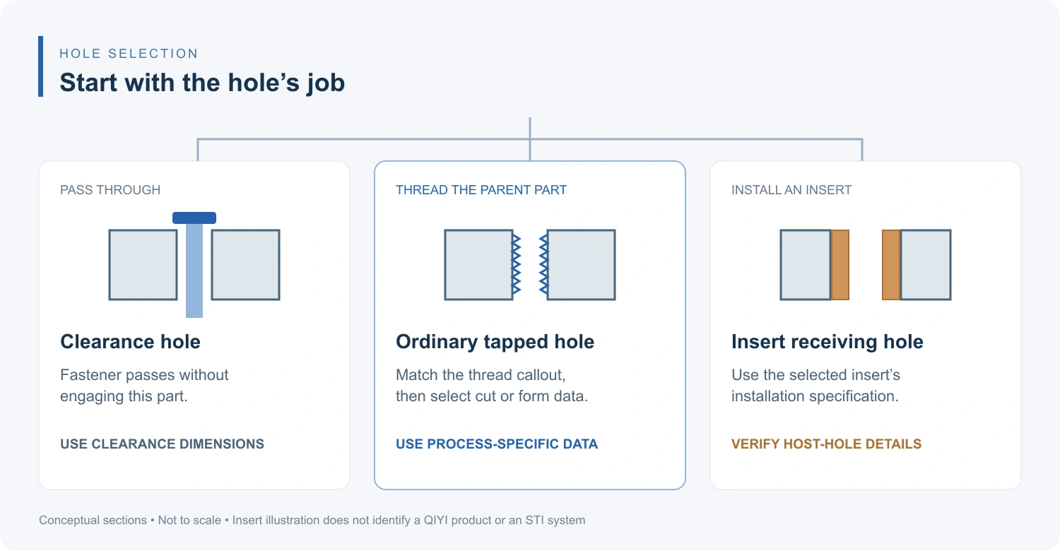
A hole that simply lets a bolt pass through needs a clearance dimension. A hole that receives a threaded insert needs the insert system’s installation dimensions. Those two jobs cannot be specified from an ordinary tap-drill row alone.
Metric tap drill size chart for cutting taps
Match both numbers in the metric designation. M8 × 1.25 and M8 × 1.00 have the same nominal diameter but require different predrills in this reference.
| Metric thread | Pitch, mm | Cutting-tap drill, mm |
|---|---|---|
| M3 × 0.50 | 0.50 | 2.50 |
| M4 × 0.70 | 0.70 | 3.30 |
| M5 × 0.80 | 0.80 | 4.20 |
| M6 × 1.00 | 1.00 | 5.00 |
| M8 × 1.25 | 1.25 | 6.80 |
| M8 × 1.00 | 1.00 | 7.00 |
| M10 × 1.50 | 1.50 | 8.50 |
| M10 × 1.25 | 1.25 | 8.80 |
| M12 × 1.75 | 1.75 | 10.20 |
| M12 × 1.50 | 1.50 | 10.50 |
Both tables use selected drill-size entries from Vergnano’s cutting-tap reference. They are a lookup subset, not the finished thread’s tolerance limits or a complete list of available pitches.
UNC and UNF drill and tap size chart
The thread labels below use inch nominal diameters and TPI. The drill column still uses millimeters; it does not give number, letter or fractional-inch drill designations.
| Inch thread | Series | Cutting-tap drill, mm |
|---|---|---|
| 1/4-20 | UNC | 5.10 |
| 1/4-28 | UNF | 5.50 |
| 5/16-18 | UNC | 6.60 |
| 5/16-24 | UNF | 6.90 |
| 3/8-16 | UNC | 8.00 |
| 3/8-24 | UNF | 8.50 |
| 1/2-13 | UNC | 10.80 |
| 1/2-20 | UNF | 11.50 |
Carry the units into the setup record. A purchase description such as “drill for 1/4 thread” leaves both the pitch and the drill system unresolved. Record the full thread, the proposed drill diameter and the selected tap together.
What the diameter-minus-pitch shortcut tells you
For metric cutting taps, nominal diameter minus pitch provides a useful first check. Dormer Pramet illustrates it with M6 × 1: 6 − 1 = 5 mm. It is a rule of thumb, so use the published tool recommendation when choosing a stock drill and approving the process.
Hole size affects the result in both directions. Too small a predrill can overload or damage the cutting tool; too large a hole can leave the internal thread outside its required dimensions. The drill, work material and actual hole produced matter alongside the nominal number.
The useful distinction is between a lookup and a released specification. A lookup identifies a candidate. The responsible machinist or process engineer checks that candidate against the tap data and drawing requirements, including how the finished thread will be accepted. Copying a table value into a drawing does not complete those decisions.
Choose the hole function before choosing the drill
Follow the component that will engage the fastener’s threads. If the fastener passes through the part and engages a nut elsewhere, the first part needs a clearance hole. If it engages the parent material, identify the thread-making process. If an insert provides the internal thread, use that insert’s receiving-hole specification.
Forming taps require their own data
A forming tap displaces material to create the thread. Its predrill must leave room for that movement, so a cutting-tap value cannot simply carry over. For example, Vergnano’s forming-tap table lists 5.55 ± 0.05 mm for M6 × 1, compared with 5.00 mm in its cutting-tap table.
That example shows why the process field belongs beside the thread callout. It is not a universal M6 forming prescription. Vergnano notes that the resulting internal diameter also depends on workpiece properties. Use the selected tool’s recommendation and hole-control requirements for the intended material.
An insert’s internal thread does not define its host hole
A screw-thread insert system may require a special receiving thread. OSG therefore publishes a separate STI tap-drill chart, with distinct cutting and forming ranges. An ordinary M6 tapping row and an M6 insert installation instruction answer different questions.
The QIYI threaded insert listing identifies nominal internal sizes and variant part numbers. Those labels alone do not establish the host-hole drill, installation method or an STI design. Identify the exact insert part number and obtain its installation drawing before machining the receiving part.
A release record that keeps the missing details visible
Consider a drawing that calls for an ordinary M6 × 1 internal thread. If the intended process is cutting, the metric table gives a 5.00 mm candidate. Before releasing it, the record should connect that number to the actual tool and part:
- Drawing requirement: full thread callout, specified thread class, required threaded depth and whether the hole is through or blind.
- Process selection: work material, selected cutting tap and its recommended predrill. If the process changes to forming, reopen the drill decision.
- Acceptance: the applicable hole and thread checks, with unresolved requirements returned to the drawing owner.
If the same assembly changes to an insert, replace the ordinary tapping entry with the selected insert’s host-hole specification. Keep the source drawing revision with that change. This preserves the relationship between the screw, the receiving component and the manufacturing instruction when the joint design evolves.
References
- Vergnano — Drill size: cutting taps. Selected metric, UNC and UNF drill-size entries.
- Dormer Pramet — Which size should I pre-drill?. Metric shortcut and process-dependent selection.
- Vergnano — Drill size: forming taps. Manufacturer-specific forming-hole example and material dependence.
- OSG — STI Tap Drill Size, Vol. 1. Separate insert-thread preparation ranges.