The difference in counterbore vs countersink selection is the shape of the recessed bearing seat. A counterbore is cylindrical with a flat bottom. A countersink is conical. When a screw head must sit within a part, the selected head geometry determines which seat to evaluate.
The hole name is only the starting point for a drawing. The designer must also define the smaller bore, recess size, depth or angle, and entry side. The assembly review then checks the head position, access for the driver and material remaining around the recess.
Counterbore vs countersink in section
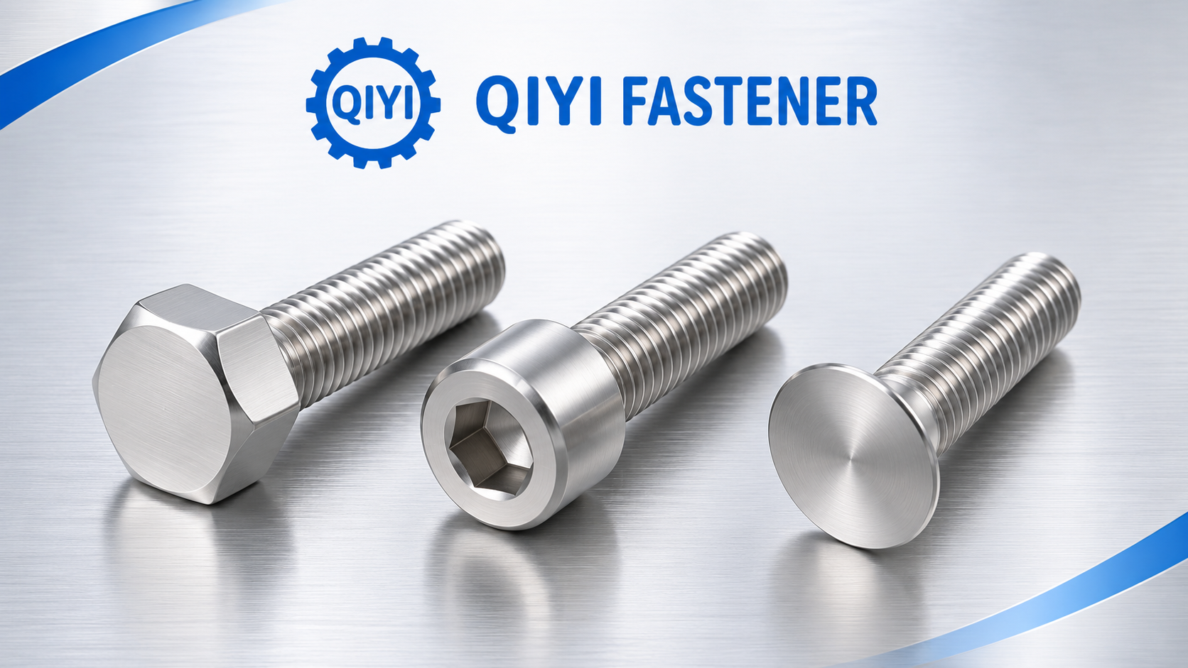
A cylindrical cap head can rest on the flat shoulder of a counterbore. A flat-head screw has a conical underside that seats against a matching countersink. The section view makes the bearing relationship easier to see than a photograph taken directly above the hole.
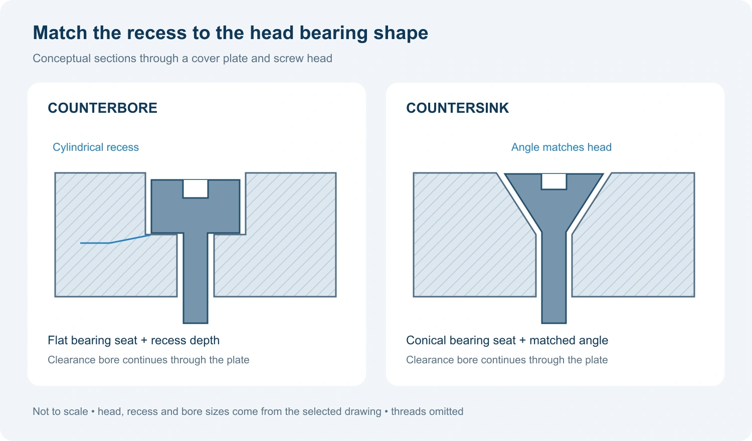
PCBWay’s technical explanation distinguishes the flat-bottom cylinder from the conical seat and lists the separate parameters needed to describe each feature. Protolabs Network connects these forms to cap-head and flat-head fasteners and discusses the need to match the countersink to the screw head.
For a buyer, that means a request for a recessed head should identify the intended fastener. A general note saying “flush screw” leaves the receiving-part designer to infer both the head form and its seat.
Specify the features that the machinist needs
A complete recess callout needs enough information to reproduce the intended interface. The table separates the principal geometry fields so a purchaser can recognize missing information before comparing quotations.
| Feature | Counterbore review | Countersink review |
|---|---|---|
| Smaller bore | Diameter and required function | Diameter and required function |
| Recess opening | Cylindrical recess diameter | Countersink opening diameter |
| Seat geometry | Flat shoulder and recess depth | Conical seat with the specified angle and extent |
| Entry side | Identify the face receiving the recess | Identify the face receiving the recess |
| Head position | Confirm the required position relative to the surface | Confirm the required position relative to the surface |
The drawing should control which dimensions define the feature and how it will be accepted. When a model and drawing use different descriptions, the designer should resolve the discrepancy before machining. A supplier’s preferred shorthand should not leave the finished geometry open to interpretation.
The smaller bore also has its own function. In the illustration, it provides clearance for the screw through the cover. The mating thread would be defined elsewhere in the assembly. Keep that distinction visible when reviewing the recess and the complete fastening arrangement.
Check the driver envelope and remaining material
A head that fits into its recess still needs practical assembly access. Check whether the selected driver can reach the socket, whether adjacent features obstruct the tool, and whether the assembled head clears moving or adjoining parts. Protolabs Network identifies tool and part clearance as separate review items.
Removing material to create either recess changes the receiving part. Review the depth and local section against the design requirements, especially where the cover is thin. A deeper recess or wider opening needs a drawing decision rather than an assumption that more clearance is always acceptable.
A cover-plate change that needs more than a new screw
Consider a hypothetical machine cover originally drawn for a cylindrical socket-head screw. Its receiving feature is a flat-bottom counterbore. During a redesign, the team proposes a flat-head screw to obtain a different surface arrangement.
The first review compares the proposed head underside with the existing seat. The head-form change introduces a different bearing geometry, so the team needs to define the proposed countersink. Copying the old recess diameter into the new drawing would leave the angle and resulting head position unresolved.
The designer then checks the smaller bore, receiving-part section and driver access with the revised fastener. The purchaser records the approved screw identity and the receiving-part drawing revision together. That lets both suppliers quote against the same interface.
If the receiving part has already been manufactured, the review must address its actual geometry before an alternative screw is approved. A revised fastener description alone does not document that decision. This example illustrates the information needed for review and supplies no machining dimensions or load rating.
Match the product drawing to the receiving hole
QIYI lists both socket-head cap screws and flat-head socket screws. These provide relevant product forms for the two seat arrangements. Confirm the complete geometry of the selected variant against the assembly drawing, including the head details needed to define the recess.
A useful quotation request includes the selected screw drawing, receiving-hole detail and required head position. It should also identify the material and finish requirements for the fastener. Any proposed alternative can then be compared field by field against the approved combination.
Release the purchase against the agreed fastener and receiving-part revisions. Keeping those references together makes it possible to explain why the selected head and hole belong in the same assembly.