Threaded inserts give host parts internal threads for a removable screw. The right insert depends on two interfaces: how the insert stays in the host material, and how the screw engages the insert. The internal thread size alone tells you little about the hole, the required installation tool, or the material around the hole.
For example, a tapped aluminum bracket, a molded plastic cover, and a hardwood assembly can all accept the same nominal machine screw. Each can require a different insert and a different way of preparing the hole. Start with the part that receives the insert, then work inward to the screw.
Choose Threaded Inserts by Host Material
Separate the product families by what retains them. The exterior of an insert may have threads, a wire coil, keys, knurling, or another retention feature. Each is made for a particular hole and installation process. A similar silhouette or matching internal thread does not establish interchangeability.
| Host and job | Insert family to check | What to verify first |
|---|---|---|
| Metal boss with a worn threaded hole | Solid threaded or wire insert designed for repair | Remaining material, approved repair geometry, drill and tap specified for the insert |
| Thin metal sheet, access from one side | Blind rivet nut, where the drawings and assembly allow it | Grip range, body shape, hole tolerance, and forming space behind the sheet |
| Wooden panel that must come apart for service | Externally threaded insert specified for that wood | Pilot hole, edge distance, grain direction, and installation method |
| Plastic boss for a removable cover | Press-in, heat-installed, ultrasonic, or molded-in design suited to the resin | Resin, boss drawing, hole tolerance, tool access, and seated height |
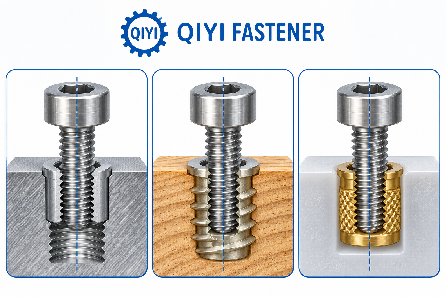
In metal, the broad distinction is whether the application has enough depth and material for a formed or tapped interface. A solid insert typically has an outer body that engages a prepared hole. A wire insert uses its own system for the prepared thread. A blind rivet nut is a different approach for sheet: it forms behind the sheet as it is installed. Verify access behind the face even when the installation tool works from the front.
For threaded inserts in wood, check the insert manufacturer’s recommendation for the actual material. The same pilot opening can behave differently in dense hardwood and soft stock. In plastic, confirm whether the material and insert series support the intended installation process. Heat-installed and press-in configurations solve different process problems. The boss must leave enough space for the chosen insert and tool without interfering with a nearby wall or rib.
Check the Screw Thread and Host Hole Separately
The internal thread specification belongs to the screw interface. Specify nominal size, pitch or threads per inch, engagement available at the installed depth, and any tolerance called out on the drawing. A fastener that starts by hand can still bottom in a blind insert or project into the enclosure. Use the assembled stack to check where the screw tip ends.
The host hole and retention requirements describe the outside of the insert. For an externally threaded insert, record the outer geometry and the specified host-hole preparation. Include drill and tap requirements where the series calls for them. For a press, formed, or heat-installed part, record the controlled hole and seating method. Do not derive that hole by adding a fixed allowance to the screw diameter. Two inserts with the same screw thread can require different holes, depth, tools, and host thickness.
A flanged body may also introduce a small step above the host face. If a cover or washer must seat flush, check the flange and the final insert height on the assembly section. Specify the reference face so the inspection team measures the installed part from the same surface the designer used.
Make repairs and new designs separate decisions
Suppose a maintenance team wants to save a worn threaded hole in a machined aluminum bracket. First determine whether the owner permits repair and whether enough material remains around the hole. The goal is to retain the mating screw and return the joint to a defined condition. Have the repair owner choose the insert series and acceptance checks, including what counts as acceptable seating and thread engagement. A close edge or a previous repair can change the decision.
Now consider a plastic instrument cover assembled and removed several times during its life. The joint starts with a clean design, so there is freedom to change the boss and choose how the insert is installed. Specify the resin and boss drawing first. During sampling, check the cover after assembly as well as the insert by itself. An insert that appears flush in an uncovered boss can still interfere with the cover or leave too little room for the screw.
The practical difference is what can be changed. Repair usually has to work within the existing surrounding geometry. A new design can give the insert the geometry and process it needs. In either case, the joint owner sets any load, torque, and durability requirements.
Release the insert and the hole as one specification
Put the host material, hole revision, insert series, mating screw, installed height, and installation method on the same checklist. Include the tooling access direction, rear clearance, and any evidence needed after installation. If the assembly uses a blind hole, state the usable depth and how bottoming will be checked. If the insert is installed before finishing, agree how the internal thread and surrounding surface will be protected.
For a catalog starting point, compare the exact dimensions and thread options on the QIYI threaded insert listing with your drawing. Ask for the insert-specific installation information before cutting the host hole. The drawing and the selected product data should describe the same two interfaces.