A set screw holds or locates a component by applying pressure through its point against another part. A common arrangement is a screw threaded through a collar or hub and tightened against a shaft. The point shape determines how that contact is made, so selecting the thread size alone leaves an important part of the joint unspecified.
For socket set screws, also called grub screws, the usual form is a headless threaded body with a recessed drive. Specify the drive and the working point separately. A hex socket describes the tool interface; cup, flat, cone and dog describe the end that meets the mating component.
Compare set screw points by the surface they meet
Start with the shaft or workpiece drawing. Identify whether the point will meet a round surface, a prepared flat, a locating depression or a mating hole. Then decide whether an indentation is acceptable. The same threaded hole can accept different point styles while producing very different contact conditions.
| Point | Contact geometry | Selection question |
|---|---|---|
| Cup | Concave end with a narrow contacting rim | Is local biting or surface marking acceptable? |
| Flat | Flat end face, suited to contact on a flat surface | Does the mating geometry provide the intended seating face? |
| Cone | Pointed taper that can penetrate the contact surface | Is this penetration or a specified locating depression part of the design? |
| Dog or extended | Smaller cylindrical extension with a flat end | Does the mating hole or slot match the extension and intended movement? |
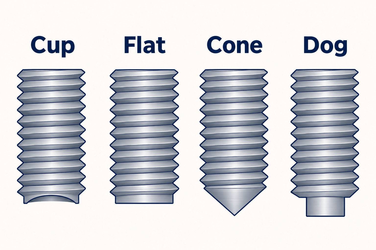
A knurled cup is a further variation with serrations around the contacting edge. Treat that detail as part of the ordered point specification. A photograph showing a cup-shaped end is insufficient to distinguish every variant, especially when the working edge is small or obscured.
Manufacturers also offer oval and specialized tipped designs. Evaluate those against their own drawings when the mating surface requires them. A short list of common points is a way to identify the interface; it is not a complete catalogue or a ranking from weakest to strongest.
Decide whether shaft marking is acceptable
Cup and cone points can penetrate or mark the mating surface. That contact may be an intended part of a fixed installation, but the permissible surface condition should be established before selecting the point. A finished shaft, a locating surface and a replaceable contact area can have different acceptance requirements.
A flat point changes the contact geometry, but its name alone does not guarantee an unmarked workpiece. Review the actual mating face, materials and tightening requirement. If a drawing requires a flat contact, verify that requirement rather than assuming a flat-ended screw automatically achieves it on every surface.
For marking-sensitive applications, purpose-designed brass or plastic tips are another option to investigate. Such products are available specifically for pressure-dent and surface-damage concerns. The selected tip material and its installation limits still need application review; “soft tipped” does not establish an allowable load or a universal damage-free result.
Write the surface acceptance requirement explicitly. For example, ask whether a local indentation is allowed at the designated contact position and how that position will be inspected. This gives the supplier a clearer task than an unrestricted request for a screw that “holds well.”
Dog points require a matched locating feature
A dog point has a cylindrical extension intended to engage a mating hole or slot. The relationship between those features belongs on the assembly drawing. Review the extension diameter, projection and position together with the receiving feature, including the intended assembled depth and available clearance.
Full-dog and half-dog descriptions identify different extension forms or lengths within a product range. Confirm the actual drawing instead of treating the names as interchangeable. Replacing a cup point with a dog point changes what must exist on the shaft; matching the thread does not resolve that difference.
For a cone point used with a locating depression, apply the same interface review. The component drawing should define the intended contact feature. Avoid leaving its shape or location to be improvised during installation, and use the assembly designer’s specification for any shaft preparation.
Include adjustment and removal in the selection
State whether the component will remain in one position or be moved during service. For an adjustable assembly, ask what happens to the contact surface after each release and reset. Include the permitted marking and the required repositioning behavior in the review, rather than assessing only the first tightening.
When replacing a fastener, inspect the point and the existing contact feature. Record visible deformation, an existing indentation or a mismatch between the installed point and drawing. A replacement should be checked against the approved specification, not selected solely because it can enter the old threaded hole.
Do not assume that a screw or tip is suitable for unlimited reuse. Obtain the selected product’s reuse or replacement guidance where repeated adjustment matters. The relevant decision is whether the point, mating surface and acceptance criteria still suit the next installation.
Check thread, length and drive as one installed interface
The purchase specification needs the full thread designation and the selected length reference. Review the screw’s installed position, the available threaded depth and where the point reaches the mating surface. A point that contacts too early or cannot reach the intended feature requires drawing review before assembly.
Confirm the required drive and matching tool. A recessed socket and the working point are at opposite ends, but both affect installation. Check tool access in the actual hub or collar and identify any requirement for the fastener to sit below the outer surface.
Use the exact manufacturer’s information for the selected size, length, material and point. Manufacturer torque guidance can have length and socket-depth conditions. A value taken from a different screw, or a general bolt table, does not establish the installation requirement for this particular set-screw assembly.
Control tightening and verify the contact
Holding behavior depends on the point-to-surface contact and the conditions of the joint. Material hardness, seating geometry and installation conditions therefore belong in the engineering review. A point-style label cannot supply a load rating for an otherwise unspecified shaft and hub.
Before production assembly, identify the governing tightening instruction and the checks that will establish acceptance. Use the specified fastener, tool and assembly condition. If the component moves after tightening, investigate the contact feature, fit and specification rather than increasing torque without a reviewed limit.
Where the inspection plan permits removal, examine whether the point contacted the intended feature and whether the resulting surface condition is acceptable. Compare observations with the drawing and supplier guidance. Record a discrepancy before substituting another point style, because the replacement can change the locating or marking behavior.
Two selection cases with different priorities
A component that must return to a defined position
In a hypothetical assembly with a specified locating hole, a dog-point candidate should be reviewed with that hole. The engineer checks the extension and receiving geometry together, then defines how engagement and final position will be accepted. The purchase description includes the point and drawing revision, not just the thread and overall length.
A stop that is repositioned during maintenance
For a hypothetical adjustable stop, begin with the permitted surface condition after repeated resets. Compare the proposed contact geometry and any designed tipped option against that requirement. Define inspection and replacement expectations before selecting a part. A previous fixed-location cup-point installation is not, by itself, evidence that the same arrangement suits repeated adjustment.
Specify the fastening function before ordering
Include the point style, full thread, length reference, drive, material and finish requirements in the enquiry. Supply the mating-component drawing, any locating feature, permitted surface marking and tightening instruction. State the service task and the acceptance checks, with unresolved items clearly identified for supplier review.
If the joint instead needs a screw head to clamp parts together, review that separate design. Qiyi’s socket head cap screw catalogue is a relevant starting point for headed fastening. Its seating and drive requirements must be checked independently; head-bearing clamping and set-screw point restraint perform different jobs.
References
Unbrako: socket set screw point drawings and product-specific installation notes
University of Florida: Fastener Handout, set-screw function and contact factors, pages 15–17
J.W. Winco: an example of brass- and plastic-tipped set screws for marking-sensitive applications
McMaster-Carr: original set-screw point and mating-surface selection guide