A shoulder bolt has a smooth, enlarged cylinder between its head and a smaller threaded end. The cylinder, called the shoulder, provides the working surface for a pivot, guide, or spacer. Specify its diameter and length separately from the thread. A bolt with the correct thread can still leave a hinge loose, bind a moving part, or bottom out before the shoulder seats.
Catalogs also call this hardware a shoulder screw or, in some tool applications, a stripper bolt. Whatever name is used, read the drawing from the head to the shoulder and then to the threaded end. Use the shoulder to define the moving or locating interface and the thread to retain it.
Read a Shoulder Bolt from Head to Thread
Start with the shoulder diameter and the bore that fits over it. A bore intended to turn or slide over the shoulder needs a design-specified clearance. A close locating joint calls for a different fit. The nominal diameters alone do not tell you the smallest clearance or whether the parts still assemble after finishing. Compare both sets of limits under the conditions in the drawing.
| Dimension | What to pair it with | What a mismatch can cause |
|---|---|---|
| Shoulder diameter | Mating bore, bushing, or bearing inner diameter | Binding or excess radial play |
| Shoulder length | Stack between the head underside and seat | Axial play or a part clamped unintentionally |
| Thread diameter, pitch, and length | Tapped part, thread engagement, and usable hole depth | Insufficient engagement or bottoming |
| Head and transition geometry | Tool access, edge relief, and bearing surfaces | Tool interference or incomplete seating |
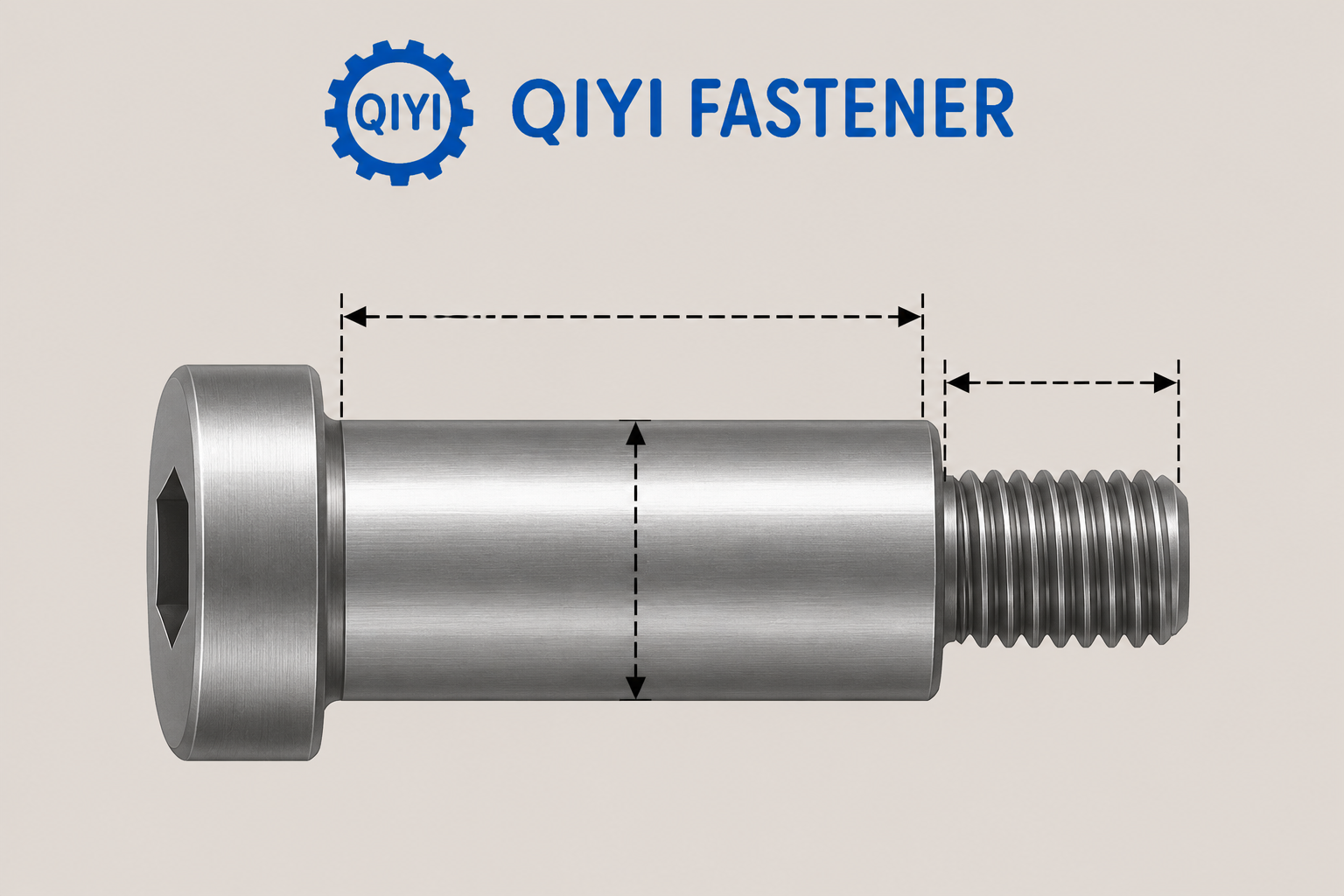
Read how the supplier defines shoulder length. It commonly runs from the underside of the head to the shoulder step. The overall length, the length under the head, and the threaded length describe different things. When issuing a new drawing or replacing a part, use the endpoints shown in the supplier or assembly drawing. A handwritten length from a removed fastener is only useful if everyone knows where it was taken.
Check whether the joint must move after tightening
The goal of a pivot is to secure the shoulder bolt while leaving the moving member free to turn as designed. Draw the section and identify the surface where the shoulder stops. Then compare the actual working stack with the usable shoulder length, including any bushing flanges and thrust washers intended in the design. If the stack is too thick, the head could clamp the moving member before the shoulder seats. If the stack is too short, the assembly may have more axial movement than intended.
Think through tolerances at both ends. One assembly with a short shoulder and thick stack is the binding case. Another with a long shoulder and thin stack is the play case. Compare those extreme combinations with the permitted movement before deciding that a nominal gap is enough. If a bearing inner ring must be held in place, its axial restraint may be different from that of a loose pivot sleeve. Use the bearing and assembly requirements to define the stop surfaces.
At the other end, check the threaded hole. A threaded tip that hits a blind hole bottom can give a misleading feeling of tightness. Verify that the shoulder contacts its intended stop and that the threaded tip clears the bottom of the blind hole. The assembly drawing or responsible engineer should identify the installation conditions and acceptable final movement.
Look at the bore entrance and shoulder transition
Check where the round shoulder transitions into the head and the threaded tip. A fillet, chamfer, or thread relief can keep a mating part from reaching the flat surface it was meant to contact. A hole that fits the straight cylinder may interfere at that transition. Compare the actual drawing geometry before specifying a counterbore, chamfer, or relief for that joint.
For replacement, inspect the mating bore as well as the old shoulder. Wear or deformation can be in either part. Use the original drawing or a new engineering disposition when the service condition has changed. Get the specified fit, finish, and shoulder tolerance from the part’s approved documentation before deciding on a replacement.
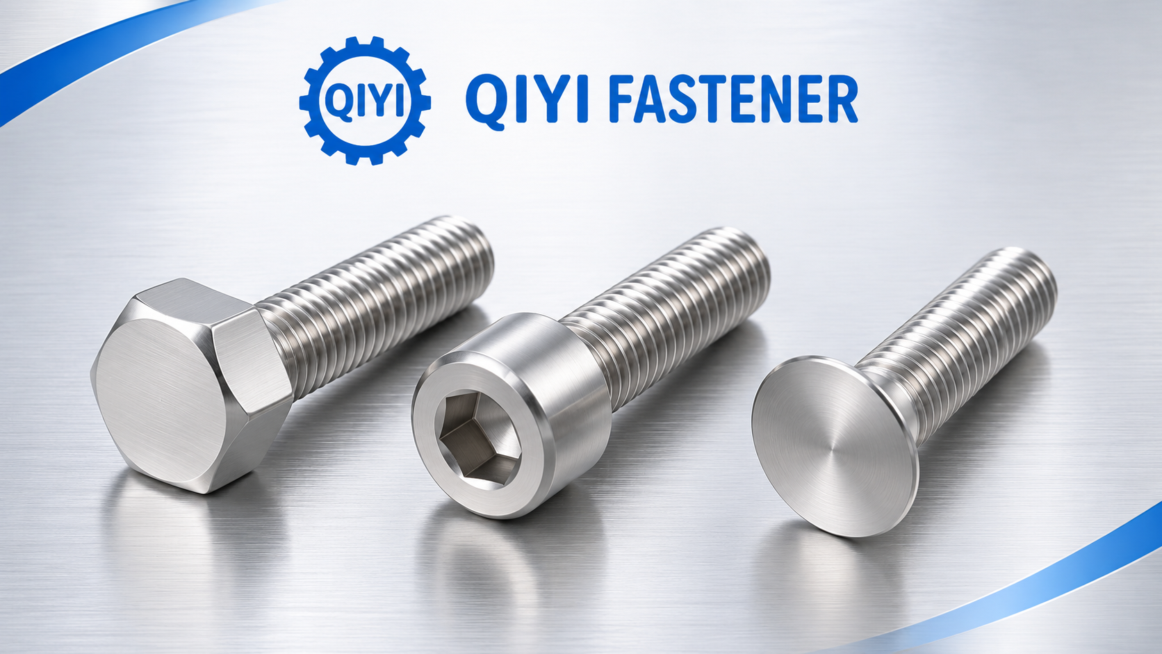
If the application only needs a screw head to clamp a rigid stack and there is no separate working journal, a headed screw may be the more relevant geometry to evaluate. The QIYI socket head cap screw catalog shows that adjacent headed configuration. Compare the drawing before substituting either design.
Check a first assembly before ordering the lot
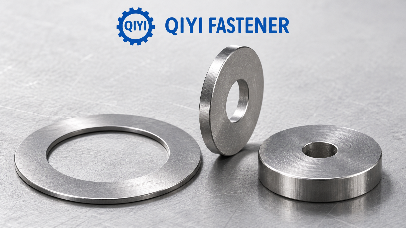
Assume a fixture finger should rotate after the fastener is seated. The drawing shows the finger running on a bushing, with a washer beneath the head. Verify that both the bushing and the washer belong in the shoulder stack and that they clear the head transition. Then verify that the shoulder contacts its stop while the threaded tip remains clear of the hole bottom. Measure movement only after you know the intended surfaces are bearing as shown.
The order should state shoulder diameter and tolerance, usable shoulder length, thread and tip geometry, head and drive details, material and finish, and the exact quantity. Point out the two mating features that matter most. Ask how the supplier will measure the shoulder dimensions and how the assembly owner will check free movement or location. Those checks are easier to agree on before a batch is released.