A nut size chart should separate the thread designation, pitch, width across flats and thickness. The nominal size identifies the thread; it is not the wrench size. The reference below covers selected metric hex nuts from a named DIN 934 product data sheet. Other nut forms and drawings can have different outside dimensions.
Use the chart to identify the dimension you need, then confirm the selected part drawing. A wrench-fit question, a mating-thread question and an assembly-height question require different entries.
Metric nut size chart: a defined hex-nut reference
All dimensions below are in millimeters. The values are selected from Böllhoff’s DIN 934 steel Class 10 hex-nut data sheet, hosted by MISUMI. Ranges retain its minimum and maximum labels. They are not universal limits for every nut carrying the same nominal thread size.
| Thread size | Pitch P | Across flats s, min–max | Thickness m, min–max |
|---|---|---|---|
| M3 | 0.50 | 5.32–5.50 | 2.15–2.40 |
| M4 | 0.70 | 6.78–7.00 | 2.90–3.20 |
| M5 | 0.80 | 7.78–8.00 | 3.70–4.00 |
| M6 | 1.00 | 9.78–10.00 | 4.70–5.00 |
| M8 | 1.25 | 12.73–13.00 | 6.14–6.50 |
| M10 | 1.50 | 16.73–17.00 | 7.64–8.00 |
| M12 | 1.75 | 18.67–19.00 | 9.64–10.00 |
The source describes DIN 934 as similar to ISO 4032 and notes changed spanner widths for several sizes. It does not make the two dimension sets identical. Keep the source and product definition attached when copying a row into a procurement note.
Read thread, tool fit and thickness separately
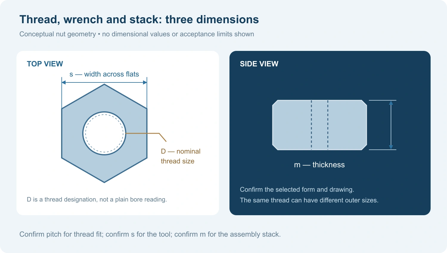
Thread size and pitch identify the mating thread requirement. For the M6 row above, the pitch entry is 1.00 mm. A record that specifies only an outside measurement leaves that thread requirement unresolved.
For the same M6 reference, the across-flats range is 9.78–10.00 mm and the thickness range is 4.70–5.00 mm. Those are two separate dimensional envelopes. A tool-access sketch should account for the selected nut’s external envelope and the tool itself. A stack-clearance sketch should account for the relevant thickness limit and the other components in that stack. The minimum thickness entry is useful when reviewing that specified lower limit; it cannot stand in for the maximum occupied height. Recording both limits also makes a supplier substitution easier to compare, because the reviewer can see which dimension changed. None of these checks identifies the thread of an unknown sample.
Width across flats is the distance between opposite flat faces. Milsons uses A/F for this dimension. Across corners is a different measurement, so a caliper placed across two corners does not directly answer the wrench-size question.
Thickness concerns the side view and the space occupied in the stack. Retain the drawing’s minimum or maximum qualification. A minimum thickness value copied into a clearance calculation as a maximum would answer the wrong question.
Why two M10 references can show different wrench sizes
In the Böllhoff reference above, M10 has a maximum width across flats of 17 mm and a thickness range of 7.64–8.00 mm. Milsons’ version 230301 chart lists its M10 × 1.5 Class 5/8/10 hex reference with 16 mm A/F and 8.4 mm height. These are distinct cited reference entries, not measurements of the same supplied part.
The practical response is to identify the required drawing, rather than merge the figures into one supposedly universal M10 row. The nominal thread description alone has not established the outside envelope. Neither reference confirms the dimensions of an unidentified nut on a workbench.
Consider a hypothetical maintenance request for a replacement nut. A technician reports the wrench that fits, while the buyer searches a screw nut size chart and chooses a nominal thread from that external measurement. The order now rests on an inference that the technician never verified.
A better record keeps each observation separate: nut form, observed external dimensions, known mating-thread designation and drawing reference. If the thread is unknown, state that it still needs identification. The selected replacement can then be compared against a definite requirement rather than a guessed catalog row.
After the thread is identified, the buyer can check tool access and stack space against the selected part’s outside dimensions. That sequence prevents an apparently successful wrench match from closing unrelated questions about thread fit or assembly clearance.
Profile nuts need their own drawing
A hex-nut dimensions chart does not define the outer body of a profile nut. QIYI’s T-Nut with Spring Leaf page lists separate profile-related families and thread options. For example, its 6- and 8-series descriptions both include M6 variants with different part references.
For that product form, include the profile drawing or exact profile requirement along with the thread and selected part number. Do not transfer a hex nut’s across-flats or thickness entry to a T-nut merely because both descriptions contain M6.
A complete dimensional enquiry should identify the nut form, nominal thread and pitch, required external envelope, material or property requirement, finish and quantity. Attach the drawing revision where available. This preserves the difference between recognizing a possible size and confirming the part that the assembly requires.