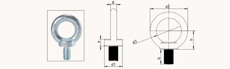
threaded vs internal profile connectors is a procurement and joint-planning question, not a product-name-only choice. Confirm the controlled drawing, exact profile geometry, joint location, and assembly constraints before requesting a quote.
Direct answer: start with the joint layout
Choose between a threaded connector and an internal profile connector by first mapping the joint geometry, the profile features that can be prepared, and the assembly path. A threaded connector may be reviewed when its required prepared interface and tightening path suit the joint. An internal profile connector may be reviewed when the joint can be accommodated inside the frame and the required preparation and assembly sequence are practical. The drawing—not the product family name—decides the final choice.
Comparison table for a drawing review
| Review point | Threaded connector | Internal profile connector |
|---|---|---|
| Joint definition | Confirm the connector interface and mating joint location. | Confirm the internal joint arrangement and available profile envelope. |
| Profile preparation | Check the prepared feature required by the selected connector. | Check any internal feature, opening, or machining required by the joint. |
| Assembly access | Confirm the tightening and inspection path before adjacent members close the joint. | Confirm the connector can be inserted, aligned, and secured in the planned sequence. |
| Visible faces | Review the final external appearance against the assembly drawing. | Review whether the internal arrangement supports the intended clean external face. |
| RFQ detail | State the connector requirement, profile, joint location, and drawing revision. | State the internal joint layout, profile, preparation, and drawing revision. |

Use access as a selection gate
Access is not a finishing detail. A connector that appears compatible in an exploded view can be impractical once panels, cross-members, or adjacent joints are in place. Mark the intended tool and insertion path on the controlled drawing. If the frame must be assembled in a different order, ask for a review before releasing the BOM.
Use the threaded connector product page and the profile connector product page to identify the relevant family, then compare the actual geometry with the drawing.
RFQ checklist
- Profile cross-section and the exact joint location
- Marked-up drawing showing the connector orientation
- Required prepared features or machining notes
- Assembly order, tool access, and any closed-frame constraint
- Visible-surface requirement and finish notes
- Quantity by assembly, project reference, and drawing revision
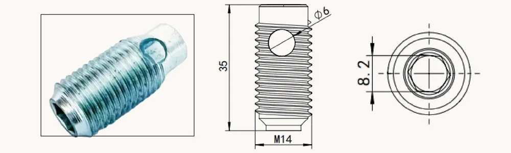
Fit Boundary
This comparison does not establish load capacity, torque, vibration performance, material grade, corrosion life, certification, or cross-brand compatibility. Do not substitute one connector family for another merely to obtain a cleaner appearance or a simpler BOM line. Final joint design and acceptance remain subject to the approved drawing and project requirements.
Request a QIYI RFQ review
Send QIYI the current drawing, BOM line, profile details, joint mark-up, quantity, and project revision through the contact form. A complete RFQ lets the requested connector family be reviewed against the actual assembly instead of a generic description.
FAQs
Can a product name alone define the connector?
No. The profile geometry, joint arrangement, preparation, access, and drawing revision must be confirmed.
Should an assembly sequence be included in the RFQ?
Yes, when access or closing the frame can affect how the connector is installed or inspected.
Can the guide establish load capacity or torque?
No. Use the approved drawing and the documentation for the exact part and project.