When the assembly drawing specifies a split lock washer under a nut, place it directly beneath that nut. If a flat washer is also specified on that side, the order is nut → split lock washer → flat washer → workpiece. Correct placement does not, by itself, verify resistance to loosening.
The washer design and assembly drawing determine how to use a lock washer. An ordinary split spring washer, a toothed washer and a proprietary locking system have different requirements. The nut-side example here concerns an ordinary split washer in a stack that the assembly specification already calls for.
How to use a lock washer: identify the design first
A split lock washer is a single ring with a cut and a helical shape. A tooth washer has teeth that contact the relevant bearing faces. The parts can both be called lock washers, but their shapes and contact requirements differ.
Read the drawing or bill of materials for the washer type and size. A similar outside diameter does not establish that a replacement has the required geometry. If the record only says “lock washer,” resolve that description before substituting a different design.
Keep the fastener, washers and receiving part together during identification. The useful question is which specified component belongs at each interface. Adding a washer to an existing stack changes that stack and needs approval under the assembly requirements.
Lock washer placement when a flat washer is specified
In the nut-side sequence above, the split washer sits next to the nut, while the flat washer sits against the workpiece. Reversing those two washers changes the prescribed contact arrangement. Albany County Fasteners illustrates this ordering in its supplier installation guide.
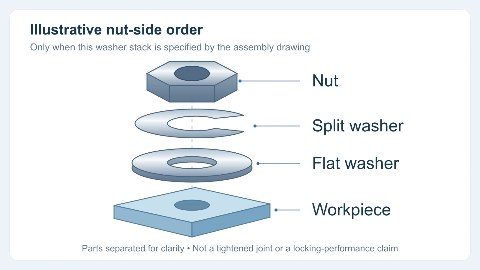
The drawing governs whether that flat washer is required. Do not add one merely to reproduce an online picture, and do not transfer this sequence to a toothed or other locking-washer design. Its intended contacting surfaces may differ.
For an unfamiliar assembly, record the existing order and compare it with the approved drawing before changing parts. A photograph can document the stack, but it cannot establish the required tightening condition or validate the original design.
Installation checks before and during tightening
Use the assembly’s specified components and tightening procedure. The following checks organize the work without inventing a torque value from the washer size or appearance.
- 1. Confirm the parts. Match the washer type and nominal size to the drawing. Check the receiving fastener and any flat washer as separate items. Keep an unidentified replacement out of the confirmed assembly set until its specification is resolved.
- 2. Check the interfaces. Confirm that the washer fits over the fastener and occupies the intended bearing position. Inspect visible damage and interference. If a part cannot sit in its specified location, resolve the mismatch before tightening.
- 3. Assemble the specified order. Place the components according to the drawing. For the illustrated nut-side example, the split washer goes between the nut and the specified flat washer. Keep the exploded-view gaps out of the actual installation interpretation.
- 4. Tighten and record the result. Follow the fastener or assembly manufacturer’s tightening specification and inspection procedure. Do not choose a generic torque, apply an assumed lubrication correction or stop early simply to leave the split washer visibly open.
How does a lock washer work, and where are the limits?
The mechanism depends on the washer design. NASA’s Fastener Design Manual, RP-1228, describes an ordinary helical split washer as acting like a spring during tightening. It also explains that the washer is normally flattened at full torque, losing the locking ability attributed to that spring action.
The manual, published in March 1990, is an engineering reference rather than a current installation rule for every industry. Its discussion is a reason to distinguish a correctly positioned split washer from a validated locking method. A visible washer gap is not a substitute for the required tightening specification.
Toothed washers use a different contact mechanism: their teeth engage the adjacent faces and can mark them. That difference does not make a toothed washer an automatic replacement for a split washer. The assembly design must establish the appropriate component and contacting surfaces.
If an assembly has a defined resistance-to-loosening requirement, request the approved locking method and its verification basis. This placement guide provides no vibration test result or approval for a particular joint.
Use the QIYI tables to check the requested washer
QIYI’s Spring Washer product page lists stainless steel, a natural finish and nominal sizes from M3 through M12. The published M5 row includes d = 5.3 mm, dk = 8.0 mm and H = 2.83 mm. Check those table symbols against the product drawing rather than treating an M5 label as the complete specification.
The separate Flat Washer page lists its own stainless-steel, natural-finish parts from M3 through M12. Use that route when a flat washer is part of the specified stack. Similar nominal size labels do not make the two washer types equivalent.
For a purchasing or replacement request, provide the fastener size, washer type, drawing reference, material, finish and required dimensions. Include the stack order and the assembly’s tightening instructions as separate information. Product dimensions identify a candidate part; they do not certify its locking performance.
After disassembly, follow the applicable inspection and replacement instructions instead of assuming that every removed washer can be reused. Record any part change against the assembly drawing so the next installer receives the same confirmed component and stack information.
References
Albany County Fasteners: nuts, washers and installation stack-up — the conditional nut-side ordering example and manufacturer tightening instructions.
NASA RP-1228: Fastener Design Manual — March 1990; printed pages 9–10 discuss helical spring and toothed washers.